
5s
+1
Submission successful!

|

| Brand Name: | DLX |
| Model Number: | Pure Nickel |
| MOQ: | 5kg |
| Price: | USD 25-80 / kg (N4/N6/Ni200, qty dependent) |
| Payment Terms: | D/A,L/C,D/P,T/T,Western Union |
| Supply Ability: | 500 tons per month |
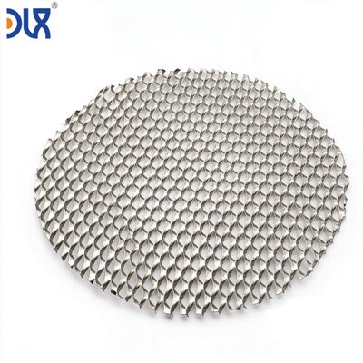
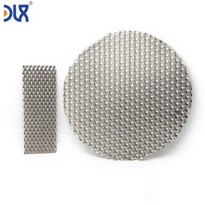
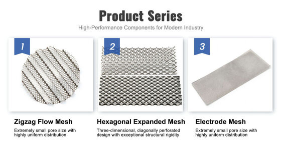
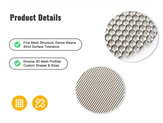
A flat mesh moves electrons. A corrugated mesh moves electrons, water, and gas — in three dimensions. At Changzhou DLX Alloy Co., Ltd., our pure nickel corrugated mesh takes a flat woven or expanded nickel substrate and forms it into a precise wave profile — creating parallel flow channels that guide water to the electrode surface and sweep product gas away from it. Unlike machined bipolar plate flow fields that cost hundreds of dollars per plate, corrugated mesh delivers the same flow distribution function at a fraction of the cost — and unlike flat mesh that relies on random gas release paths, the engineered corrugation geometry ensures every square centimeter of electrode area sees both fresh water delivery and unobstructed gas removal. Custom pitch, amplitude, sheet size, and substrate type produced to your electrolyzer cell design.
In a PEM electrolyzer operating at 2 A/cm², the anode produces approximately 12 milliliters of oxygen per minute per square centimeter of active area. That oxygen must escape from the catalyst layer, through the porous transport layer, and out of the cell — all without blocking fresh water from reaching the catalyst. A flat mesh offers a 2D plane: water and gas compete for the same space, in the same plane, creating mass transport limitations that cap current density.
A corrugated mesh separates the flows into two functional zones: the channel valleys carry water to the electrode, and the channel peaks create headspace for gas to collect and exit. The corrugation pitch determines how many parallel flow paths exist per centimeter of electrode width. The corrugation height determines the cross-sectional area of each flow channel — and therefore the maximum gas flow rate before bubble coalescence blocks the channel. Together, pitch and height define the flow field hydraulics — and they are both parameters you specify on your drawing.
| Parameter | What It Controls | Typical Electrolyzer Range | Trade-Off |
|---|---|---|---|
| Pitch (peak-to-peak spacing) | Number of parallel flow channels per unit width | 2.0–8.0 mm | Smaller pitch = more channels = better water distribution but higher pressure drop. Larger pitch = fewer wider channels = lower pressure drop but potential for stagnant zones between channels. |
| Amplitude (peak-to-valley height) | Channel cross-sectional area — determines maximum gas flow capacity per channel | 0.5–3.0 mm | Higher amplitude = deeper channels = better gas removal at high current density but increased cell thickness and ohmic resistance through the taller mesh. |
| Profile shape | Flow pattern — laminar vs turbulent mixing at the electrode surface | Sinusoidal wave, trapezoidal corrugation, square channel | Sinusoidal: smooth flow, lowest pressure drop. Trapezoidal: flat peak for better contact with adjacent layer. Square: maximum channel volume for high gas production rates. |
| Substrate mesh type | Surface area, electrical contact points, water permeability through the mesh itself | Woven (plain/twill/Dutch) or expanded metal — selected based on function | Woven substrate: higher surface area for electrode contact. Expanded substrate: fewer contact resistance points, uniform compression. |
| Substrate wire diameter or strand width | Open area within the mesh plane — water and gas can also flow through the mesh openings, not just around the corrugation channels | Wire: 0.10–0.40 mm; Strand: 0.4–0.8 mm | Finer wire = more open area for through-plane flow but less mechanical rigidity under stack compression. |
| Stack Position | Component It Replaces or Supplements | Why Corrugated Mesh |
|---|---|---|
| PEM anode flow field / diffuser | Machined titanium bipolar plate with flow channels | Corrugated nickel mesh inserted between the flat bipolar plate and the PTL creates flow channels without machining. Replaceable — if the mesh degrades, you swap the mesh, not the bipolar plate. |
| PEM cathode diffuser | Sintered titanium felt or carbon paper GDL | Corrugated mesh provides both gas diffusion and flow channeling in one component. Higher open area than sintered felt at equivalent thickness — lower gas-side pressure drop. |
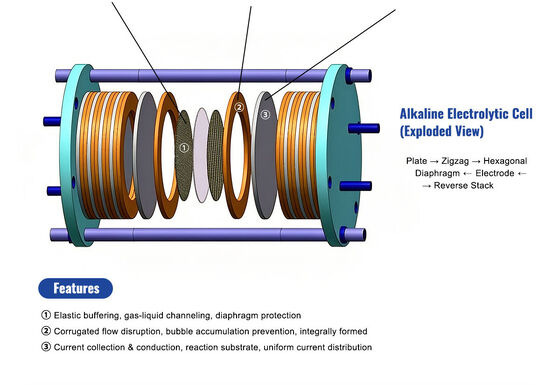
| Alkaline zero-gap electrode spacer | Flat woven mesh + separate spacer frame | The corrugation height sets the electrode gap — no separate spacer component. The mesh performs three functions simultaneously: current collection, gas-liquid separation, and gap control. |
| Bipolar plate flow field (low-cost stack design) | Entire machined flow field plate | Flat nickel sheet bipolar plate + corrugated mesh flow field on each side = functional equivalent of a machined flow field at significantly lower manufacturing cost. For stacks targeting <$300/kW, this is the enabling cost reduction. |
Most companies that offer corrugated mesh do not make the mesh. They buy flat mesh, run it through a corrugating machine, and ship it. The nickel wire chemistry, the weave integrity, the annealing condition — none of it is under their control. When your cell performance varies from batch to batch and you trace the root cause to the mesh, you discover that the mesh supplier changed their wire source without telling anyone, and the new wire has 0.2% more iron than the qualification batch.
At DLX, the chain is linear and transparent. Our melting furnace produces pure nickel ingot to your specified grade. Our rolling mill or drawing line produces the strip or wire that becomes your flat mesh substrate. Our weaving loom or expanding press makes the flat mesh. Our gear-former corrugates it to your pitch and amplitude specifications. And our controlled-atmosphere furnace anneals the finished corrugated mesh to lock in the profile geometry and relieve forming stresses. Five steps, one facility, one quality system, one point of accountability.
Source: DLX Alloy product catalog. Chemistry certified from ingot through finished corrugated mesh.
| Element (%) | N4 | N6 | Ni200 | Ni201 |
|---|---|---|---|---|
| Ni+Co | ≥99.9 | ≥99.5 | — | — |
| Ni | — | — | ≥99.2 | ≥99.0 |
| Fe | ≤0.04 | ≤0.1 | ≤0.4 | ≤0.4 |
| Cu | ≤0.015 | ≤0.1 | ≤0.25 | ≤0.25 |
| C | ≤0.01 | ≤0.1 | ≤0.15 | ≤0.02 |
| Si | ≤0.03 | ≤0.1 | ≤0.35 | ≤0.35 |
| Mn | ≤0.002 | ≤0.05 | ≤0.35 | ≤0.35 |
| S | ≤0.001 | ≤0.005 | ≤0.01 | ≤0.01 |
| Parameter | Your Specification | Our Capability |
|---|---|---|
| Nickel grade | N4, N6, Ni200, Ni201 | Chemistry locked to your approved heat |
| Substrate type | Woven (plain, twill, Dutch) or expanded metal | Both manufactured in-house — select based on function |
| Wire diameter (woven) / strand width (expanded) | Per your drawing | Wire 0.10–0.40 mm; strand 0.4–0.8 mm |
| Corrugation pitch | 2.0–8.0 mm ±0.1 mm | Custom forming roll cut to your pitch |
| Corrugation amplitude | 0.5–3.0 mm ±0.05 mm | Roll gap precision controlled |
| Profile shape | Sinusoidal or trapezoidal | Roll tooth profile cut to your waveform |
| Sheet dimensions | Custom L * W to cell frame | Cut after corrugation — channels align parallel to your flow direction |
| Corrugation orientation | Channels parallel to gas flow direction | Oriented as specified on your drawing |
| Post-form treatment | Annealed (standard) or as-formed | Annealed recommended for dimensional stability under compression |
| Stage | Inspection | Acceptance Criterion |
|---|---|---|
| Ingot chemistry | OES — full element analysis | Per your grade specification. Fe and Cu at ppm levels verified. |
| Flat mesh substrate | Wire/strand dimension, mesh count or LWD, visual for defects | Per your substrate specification — inspected before corrugating. Defective substrate is scrapped before value is added. |
| Corrugation geometry | Pitch: optical comparator — 10 measurements across sheet width. Amplitude: dial indicator on granite surface — 5 measurements across sheet. | Pitch within ±0.1 mm of drawing. Amplitude within ±0.05 mm of drawing. Out-of-tolerance sheets are scrapped. |
| Post-anneal dimensional stability | Amplitude re-measured after annealing. Test compression — mesh compressed to 80% of nominal height, released, height re-measured. Springback must be ≤5%. | Height recovery within 5% after compression. Mesh that takes a compression set is scrapped — it will lose channel height in the stack over time. |
| Sheet dimensions | L * W ±0.5 mm. Edge inspection for burrs. | As drawing. Burr-free edges — no sharp points that can puncture adjacent layers. |
| Documentation | EN 10204 3.1 MTC + substrate inspection report + corrugation geometry report + compression springback test + certificate of conformance | Complete traceability from nickel ingot through finished corrugated flow field mesh. |
Third-party inspection by SGS, BV, or TÜV available. Free sample of 5 sheets for electrolyzer OEM drawing evaluation.
| Sheet protection | Corrugated sheets are stacked with the corrugation channels aligned — peaks nest into valleys of the adjacent sheet with a single sheet of acid-free tissue between them. This prevents the stack height from being crushed under its own weight during transit. Stacked between rigid backing boards, wrapped in VCI film, and sealed. |
| Crating | Flat-packed in plywood crate with internal foam-lined bracing that contacts the sheet edges, not the corrugated faces — no compression of the corrugation profile from crate contact. Desiccant packs inside sealed polyethylene bag. |
| Identification | Grade, ingot heat number, substrate type, pitch * amplitude, profile shape, sheet dimensions, sheet count, DLX traceability code. Your drawing number on exterior crate label. |
| Sample MOQ | 5 sheets — free for electrolyzer OEM evaluation with drawing. |
| Production MOQ | 50 sheets per drawing number. Forming roll tooling amortized across first production order or billed separately depending on order volume. |
| Lead Time | Existing tooling (pitch + amplitude combination): 1–2 weeks trial, 3–4 weeks production. New forming roll fabrication: add 3–4 weeks for tooling. |
| Shipping | Air (DHL, FedEx) for trial; sea (FCL) for production. |
| Payment | T/T for trial; T/T or L/C at sight for production. |
Start with your target current density and gas production rate per cell. Higher current density requires more gas removal capacity — increase amplitude or decrease pitch to add channel cross-sectional area. Your flow modeling (CFD) should guide the initial parameters. If you do not have a CFD model, we can provide sample sheets at 2–3 pitch/amplitude combinations for empirical single-cell testing. Most customers converge on their optimal geometry within two iterations.
Standard is channels parallel to the sheet length — this aligns with the natural flow direction from inlet to outlet in most cell designs. If your design requires channels at an angle (e.g., 45° for cross-flow), sheets are cut after corrugation at the specified angle. The cut edges will intersect the corrugation channels at an angle — some open channel ends will be exposed. We can discuss whether this is acceptable for your design or whether the forming roll orientation should be adjusted.
Total thickness (substrate thickness + corrugation amplitude): minimum approximately 0.7 mm for woven substrate with 0.10 mm wire and 0.5 mm amplitude. The practical minimum is driven by the substrate wire diameter — the wire must survive the bending at the corrugation peaks without fracturing. For expanded metal substrate, minimum total thickness is approximately 0.9 mm with 0.15 mm sheet and 0.6 mm amplitude.
No — our forming rolls are polished to prevent surface marking on the nickel. The mesh bends around a controlled radius at each peak and valley. Post-form annealing relieves any surface stresses from bending. The surface condition of the finished corrugated mesh is equivalent to the surface condition of the flat substrate — if the substrate was bright annealed, the corrugated mesh is bright annealed.
Yes. Expanded nickel mesh can be corrugated with the same forming process. The key difference is that expanded mesh has directionality — the diamond pattern has a long-way and short-way orientation. The corrugation channels should be aligned with the LWD direction for maximum mechanical integrity through the forming rolls. We will confirm the optimal orientation during drawing review.


 english
 français
 Deutsch
 Italiano
 Русский
 Español
 português
 Nederlandse
 ελληνικά
 日本語
日本語
 한국
한국
 中文
中文
 العربية
 हिन्दी
 Türkçe
 indonesia
 tiếng Việt
 ไทย
ไทย
 বাংলা
বাংলা
 فارسی
فارسی
 polski
