
5s
+1
Submission successful!

|
| Brand Name: | DLX |
| Model Number: | Pure Nickel |
| MOQ: | 5 |
| Price: | Custom orders based on provided images |
| Payment Terms: | L/C,D/A,D/P,T/T,Western Union |
| Supply Ability: | 500 tons per month |
ISO9001 Factory Direct | Since 2002 | N4/N6/Ni200 | Custom to Your Drawing | 5-Sheet Free Sample
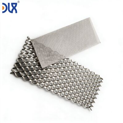
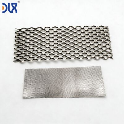
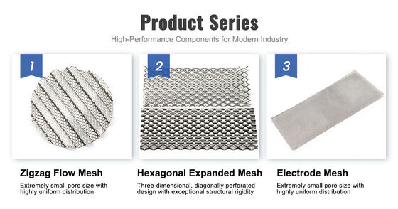
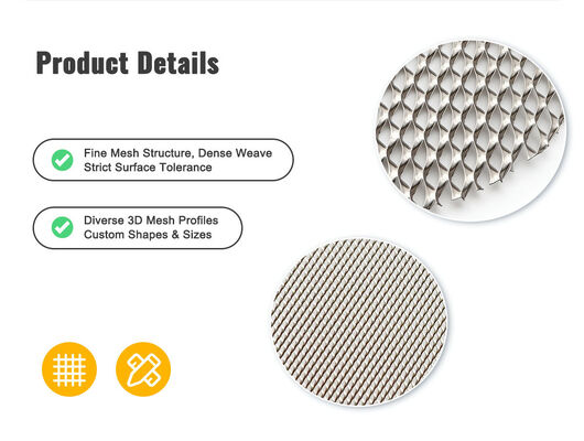
Your electrolyzer cell design is proprietary. Your mesh specification is part of your IP. The last thing you need is a mesh supplier who tries to sell you whatever is sitting on their shelf. At Changzhou DLX Alloy Co., Ltd., we manufacture pure nickel expanded mesh to your technical drawing — not to our standard catalog. The sheet thickness, strand width, LWD, SWD, open area percentage, sheet outer dimensions, edge condition, surface roughness, flatness tolerance, and post-expansion heat treatment are all produced to match the values on your print. We hold the nickel chemistry from our own ingot, roll the sheet to your thickness in our own mill, slit and stretch to your LWD and strand geometry, anneal to your hardness specification, and inspect to your acceptance criteria. This is contract manufacturing for electrode components — not off-the-shelf mesh sales.
| Phase | What Happens | What You Receive |
|---|---|---|
| 1. Drawing review | Our engineering team reviews your print: sheet thickness, strand width, LWD, SWD, open area, sheet dimensions, edge condition, flatness, surface finish, grade. If any parameter conflicts with another (e.g., strand width + LWD combination is mechanically unstable), we flag it before we cut metal — not after. | Manufacturing feasibility report (24–48 hours). If adjustments are needed, proposed alternative parameters with reasoning. |
| 2. Tooling design | For new LWD/strand width combinations: slitting die set designed and fabricated. For existing tooling: die set confirmed against your parameters. | Tooling schedule: 3–4 weeks for new dies; ready immediately for existing tooling. |
| 3. First article production | Nickel sheet rolled to your thickness from our ingot. Die set mounted. Expansion trial: 5–10 sheets produced. Each sheet measured for LWD, SWD, strand width, open area, thickness, flatness, and dimensions. | First article inspection report (FAIR) with measured values vs your drawing tolerances. Production feasibility confirmed or parameter adjustments recommended. |
| 4. Pre-production samples | After FAIR approval: 20–50 sheets produced under production conditions. Annealed, flattened, inspected, packed, shipped. | Pre-production samples for your single-cell or short-stack testing. Full inspection data per sheet. |
| 5. Production qualification | After your electrochemical testing confirms mesh performance: production tooling finalized, inspection checkpoints documented, process parameters locked. | Qualified production process. Future orders manufactured to identical parameters without re-qualification. |
| Drawing Callout | Typical Electrolyzer Spec | Our Manufacturing Tolerance | Inspection Method |
|---|---|---|---|
| Material grade | N4 / N6 / Ni200 / Ni201 | Per ASTM B160 or tighter — chemistry locked to your approved heat | OES per melt; PMI verification per production batch |
| Sheet thickness | 0.15–0.50 mm | ±0.01 mm from cold rolling line | Micrometer — 5 points across coil width per coil |
| Strand width | 0.4–1.2 mm | ±0.05 mm | Optical comparator — 5 measurements per sheet, random locations |
| LWD (long way of diamond) | 1.5–6.0 mm | ±0.15 mm | Steel rule + optical check — 10 diamonds measured per sheet |
| SWD (short way of diamond) | 1.0–3.5 mm | ±0.15 mm | Optical comparator — correlated with LWD measurement locations |
| Open area % | 30–65% | Calculated from measured LWD + SWD + strand width; verified by optical area analysis on sample sheet | Optical measurement system — reported per production batch |
| Sheet dimensions (L * W) | Per cell frame | ±0.5 mm on cut dimensions | Steel rule or CMM — every sheet measured before packing |
| Flatness | ≤0.2 mm deviation from plane per 100 mm | Verified post-anneal on granite surface plate | Feeler gauge under granite surface plate — per sampling plan |
| Edge condition | Burr-free, no protruding strands | Visual at 5* magnification; tactile check | Microscope + physical edge rub test — every sheet |
| Surface roughness (Ra) | Per drawing (typically 0.4–1.6 μm Ra for coating) | As specified — achieved through final rolling pass or post-expansion treatment | Profilometer — per sampling plan |
| Hardness | Per drawing (typically ≤65 HRB annealed) | Verified post-anneal | Rockwell B or Vickers microhardness — per batch |
Expanded mesh leaves our expanding press with a characteristic surface — the strands show micro-roughness from the slitting and stretching process. For some electrolyzer applications, this as-expanded surface is ideal — it increases geometric surface area for catalyst adhesion. For others, it creates coating thickness variation that reduces catalyst utilization. We offer four surface conditions, selectable on your drawing:
| Surface Condition | Process | Result | Best For |
|---|---|---|---|
| As-expanded | No post-treatment after expansion and annealing | Natural micro-texture from slitting + stretching. Slightly matte. Ra typically 0.8–2.0 μm. | Electrodeposited Raney nickel coating — rough surface improves mechanical interlock of the coating |
| Bright annealed | Controlled-atmosphere anneal after expansion, no additional mechanical treatment | Smooth, reflective surface. No oxide. Ra typically 0.3–0.6 μm. Lowest surface contamination. | PEM cathode GDL — where iron contamination must be minimized and uniform contact with the catalyst layer is critical |
| Conditioned (Ra-specified) | Post-expansion surface treatment to achieve target Ra range per your drawing | Ra controlled to ±0.2 μm of target. Surface profile engineered for coating adhesion optimization. | When your coating process qualification specifies a surface roughness window — and you need every batch to fall within it |
| Pre-oxidized | Controlled oxidation after annealing to form uniform NiO layer | Uniform dark green-grey oxide. Surface passivated — no further oxidation during initial cell conditioning. | When you want to eliminate the initial conditioning cycle in your stack commissioning procedure |
In 2019, a European PEM electrolyzer manufacturer sent us a 3-page technical drawing for an expanded nickel mesh — sheet thickness 0.20 mm, strand width 0.5 mm, LWD 2.8 mm, open area 52%, N4 grade, bright annealed, flatness 0.15 mm per 100 mm, Ra 0.4–0.8 μm, sheet dimensions to their cell frame, burr-free edges. They had been buying this mesh from a general expanded metal supplier who met the dimensional spec but could not control the nickel chemistry or the surface iron contamination. Every batch required incoming inspection, and roughly 15% of batches were rejected for surface contamination found during their coating process qualification.
We looked at the drawing and realized: we already control the nickel chemistry from our own ingot. We already cold roll pure nickel strip to thickness tolerances tighter than 0.20 ±0.01 mm. We already anneal in controlled atmosphere for bright, oxide-free surface. What we did not have was the expanding press — so we invested in one. It took six months from equipment installation to first article approval on that customer's drawing. Their incoming rejection rate dropped from 15% to zero. That customer is still buying from us today, now at production volumes five times their 2019 requirement.
That is the business we are in. Not selling mesh. Solving the problem between your drawing and your electrode.
Source: DLX Alloy product catalog. Chemistry certified from ingot through finished mesh — per your drawing requirements.
| Element (%) | N4 | N6 | Ni200 | Ni201 |
|---|---|---|---|---|
| Ni+Co | ≥99.9 | ≥99.5 | — | — |
| Ni | — | — | ≥99.2 | ≥99.0 |
| Fe | ≤0.04 | ≤0.1 | ≤0.4 | ≤0.4 |
| Cu | ≤0.015 | ≤0.1 | ≤0.25 | ≤0.25 |
| C | ≤0.01 | ≤0.1 | ≤0.15 | ≤0.02 |
| Si | ≤0.03 | ≤0.1 | ≤0.35 | ≤0.35 |
| Mn | ≤0.002 | ≤0.05 | ≤0.35 | ≤0.35 |
| S | ≤0.001 | ≤0.005 | ≤0.01 | ≤0.01 |
| Drawing Requirement | Our Inspection | Documentation You Receive |
|---|---|---|
| Chemistry | OES per ingot; PMI spot check per production batch | EN 10204 3.1 MTC with full element breakdown |
| Dimensional (LWD, SWD, strand, thickness, sheet size) | Per sampling plan agreed at qualification; 100% inspection available on request | Dimensional inspection report — measured vs drawing nominal, per batch |
| Open area % | Optical measurement system; calculated from measured geometry; verified by area analysis | Open area report per batch |
| Flatness | Granite surface plate + feeler gauge; per sampling plan | Flatness report — max deviation recorded |
| Edge condition | 5* magnification visual; tactile burr check; 100% per sheet | Edge inspection sign-off per sheet lot |
| Surface roughness (if specified) | Profilometer; 3 measurements per sample sheet; per sampling plan | Ra report per batch |
| First article | Full dimensional + visual + flatness on every sheet in first article batch | FAIR — AS9102 format or your format |
Third-party inspection by SGS, BV, or TÜV available. Drawing-controlled manufacturing with full documentation package on every shipment.
| Sheet protection | Each sheet interleaved with acid-free tissue paper. Stacked flat between rigid, moisture-resistant backing boards. Entire stack wrapped in VCI anti-corrosion film prior to crate packing. No metal-to-metal contact. No sheet movement during transit. |
| Crate construction | Seaworthy plywood crate with internal bracing sized to your sheet dimensions and order quantity. Crates labeled with your drawing number, our batch number, and DLX traceability code. |
| Documentation package | EN 10204 3.1 MTC + dimensional inspection report + open area report + flatness report + edge inspection sign-off + Ra report (if specified) + certificate of conformance + packing list. Organized per your documentation requirements. |
| Sample MOQ | 5 sheets for drawing evaluation — free of charge for qualified electrolyzer OEMs. |
| Production MOQ | 50 sheets per drawing number. |
| Lead Time | Existing tooling: 1–2 weeks for trial, 3–4 weeks for production. New tooling: 4–6 weeks including die fabrication and first article. |
| Shipping | Air (DHL, FedEx) for samples and urgent orders; sea (FCL) for production — crates optimized for container utilization. |
| Payment | T/T for trial; T/T or L/C at sight for production orders. |
PDF is preferred for initial review. DXF or DWG for tooling design if the mesh geometry is complex or includes features beyond standard expanded diamond pattern. For standard expanded mesh specifications, a dimensional table on the drawing is sufficient — we do not need a 3D model of the diamond geometry, though we accept them if you have them.
This happens — typically when strand width and LWD are specified independently and the combination cannot be achieved with expanding tooling at the specified sheet thickness. Our engineering team flags the conflict during drawing review (Phase 1), before any metal is cut. We propose the nearest achievable combination with an explanation of the constraint. You decide whether to adjust the drawing or proceed with the achievable combination for trial evaluation.
For sheet thickness 0.20 mm and above, 0.15 mm per 100 mm is achievable with post-anneal flattening. Below 0.20 mm sheet thickness, the mesh becomes increasingly flexible and flatness measurement precision becomes the limiting factor rather than our capability. Contact us with your target tolerance and sheet thickness — we will confirm feasibility.
Each drawing revision triggers a review against the previous revision. If the change is limited to sheet dimensions, no re-tooling is required — the new dimension is applied at the cutting stage. If LWD, SWD, or strand width change, new tooling may be required. We communicate the impact (tooling lead time, any cost change, re-qualification requirement) within 48 hours of receiving the revised drawing. All production after the revision date is manufactured to the new revision — the previous revision is archived in our document control system.
Yes. If your supplier quality manual requires specific inspection checkpoints, measurement methods, sampling plans, or documentation formats beyond our standard package, we incorporate them into your production process during qualification. Examples from existing customers: AS9102 First Article Inspection format, PPAP Level 3 documentation, customer-specific AQL sampling tables, and batch-level certificate of analysis with customer-defined format. Provide your supplier quality requirements with your drawing — we will confirm compliance scope during drawing review.


 english
 français
 Deutsch
 Italiano
 Русский
 Español
 português
 Nederlandse
 ελληνικά
 日本語
日本語
 한국
한국
 中文
中文
 العربية
 हिन्दी
 Türkçe
 indonesia
 tiếng Việt
 ไทย
ไทย
 বাংলা
বাংলা
 فارسی
فارسی
 polski
